Motor Thermistor Wiring Diagram
The thermistor has to be connected to a control circuit, which can convert the resistance signal, which again has to disconnect the motor. Each component should be set and connected with different parts in particular way.
43 Motor Thermistor Wiring Diagram Wiring Diagram Source Online
Wiring a 2 wire thermostat is pretty straightforward.
Motor thermistor wiring diagram. Brake = 230v brake control: 4 wire motor connection diagram. If not, the arrangement will not function as it should be.
Furnace blower motor wiring diagram wiring diagram is a simplified adequate pictorial representation of an electrical circuit it shows the components of the circuit as simplified shapes and the knack and signal connections in the middle of the devices. But, it does not mean connection between the cables. 1 termi nal on the remote.
As stated earlier, the lines at a baldor motor wiring diagram signifies wires. (when the voltage changes rapidly from 100% to 0% of rated voltage). Circuits connected to all digital and analogue inputs of the drive are protected against contact and insulated with basic insulation (the same voltage level as the drive main circuit) from other low voltage circuits.
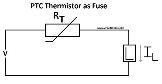
Ptc thermistors motor temperature sensors with their very steep curves are very suitable for the monitoring of temperature limits and consequently for switching on a fan when a particular temperature is reached. Compressor and fan motor furnished with inherent thermal protection. The main advantages of thermistors are:
Symbols are electrical representation only. There is double or reinforced insulation between the thermistor and live parts of the motor. If we put it simply, a 2 wire thermostat is one that has only 2 wires coming out of its backside.
2 wire thermostat wiring diagram heat only. Motor configured for high voltage. Ptc thermistors motor temperature sensors with their very steep curves are very suitable for the.
And the two stars which come out of the starting winding of the motor are mostly black wire. Motor winding thermistor wiring diagram. Their small size allows them to be installed in direct contact with the stator winding.
A wiring diagram is a simplified traditional pictorial representation of an electrical circuit. Brake voltage matches the low motor voltage. 230v / 460v motor configured for 460v ( ) • brake voltage is 230v [1] motor terminal board [4] sr current relay [2] supply leads [5] terminal strip
The nest thermostat is not only the best 2 wire wifi thermostat but it is one of the best wifi thermostats you can get for your home. Occasionally, the cables will cross. W22xd lv flameproof motor ex proof yst redüktör weg.
For example , in case a module will be powered up and it sends out a new signal of fifty percent the voltage in addition to the technician will not know this, he'd. Usa u5 v5 w5 l1 l2 l3 u2 v2 w2 t6 t1 t2 t3 t4 t5 u1 v1 w1 t7 t8 t9 u5 v5 w5 motor connection diagrams uscs 0100. Injunction of two wires is usually indicated by black dot in the junction of two lines.
Electric motor technical catalog nema three phase thermistor relay working principle the basics of built in protection specification guide weg free cad models w22 general motors manualzz wiring diagrams diagram dc teao tefc cooling tower w22xd lv flameproof ex proof soft starter arrancador suave tec ie2. There'll be principal lines which are represented by l1, l2, l3, and so on.

Unique Honeywell Baseboard Heater thermostat Wiring Diagram diagram diagramtemplate
Motor Winding Thermistor Wiring Diagram Wiring Diagram
43 Motor Thermistor Wiring Diagram Wiring Diagram Source Online

THERMISTOR PROTECTION RELAY, 24VAC Lovato Electric


Lennox Furnace Blower Motor Wiring in 2020 Thermostat wiring, Carrier heat pump, Heat pump

Wiring Diagram For Reliance Dual Thermostat schematic and wiring diagram

Wiring A Single Pole Toggle Switch Most Double Pole Thermostat Wiring Diagram On Stats, Bright

Motor Winding Thermistor Wiring Diagram Wiring Diagram
Motor Thermistor Wiring Diagram Wiring View and Schematics Diagram
47 3 Phase Motor Thermistor Wiring Diagram Wiring Diagram Source Online

39 3 Phase Motor Thermistor Wiring Diagram Wiring Diagram Online Source
Motor Winding Thermistor Wiring Diagram Wiring Diagram
43 Motor Thermistor Wiring Diagram Wiring Diagram Source Online

Motor Winding Thermistor Wiring Diagram Wiring Diagram

Wiring For Furnace And Evap. Cooler With Wifi Thermostat HVAC DIY Chatroom Home Improvement

47 3 Phase Motor Thermistor Wiring Diagram Wiring Diagram Source Online

Reliance Motor Wiring Diagram Thermistor Wiring Diagram Baldor Motor Wiring Diagram Wiring

Motor Thermistor Wiring Diagram
Thermistors, the Magic Behind Smooth Acceleration